Agile Modeling Techniques for Story Writing
Rob Pak ·
On those occasions, I supplement my list in Tracker with another technique for capturing user stories. It involves modeling using a UML IDE. Primarily, I use Activity Diagrams because they capture behavior using ‘actions’ and allow for flow. Because activity diagrams are essentially flow charts, they provide a simple comprehension mechanism for all customers regardless of their technical background. I usually display my desktop in the conference room using a projector and interactively add elements to the diagram as I receive customer input. For demonstrating modeling techniques, I will use a ‘Music Store’ web application as an example.
Summary of Steps:
- Create an Activity Diagram from a High-Level Functional Requirement.
- Capture Customer Input for Identified Functional Requirement.
- Model Flow for Activity, Link Actions with Diagram Elements.
- Aggregate Similar Actions to Separate Activity.
- Convert Activity Diagram into User Stories.
- Repeat Steps until all Functional Requirements are Exhausted.
Step 1: Create an Activity Diagram from a High-Level Functional Requirement
Start with a known high-level functional requirement and create an Activity diagram. When starting, I will identify a large chunk of functionality that I know to be required for the project and use that as a discussion point with the audience. For my sample Music Store project, I would choose ‘Browsing the Inventory’ as a large piece of functionality. At this point, the audience might begin to shout out other large pieces of functionality (i.e. ‘Customers can create accounts’, ‘Employees can add to inventory’). If this occurs, I like to create empty Activity diagrams named appropriately. These large pieces of functionality will eventually be decomposed into smaller, more manageable, Activities and Actions.
Step 2: Capture Customer Input for Identified Functional Requirement
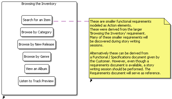
Gather input from the audience regarding this Activity / functional requirement and capture pertinent information as Actions. Essentially, what you are trying to do here is decompose the larger ‘Browsing the Inventory’ functional requirement into smaller ones. Make an attempt to name each of the Actions with story-like syntax (i.e. ‘As a <role> I can <result> so that <benefit>’). The goal of this step is to create a catalog of smaller functional requirements so that you can start modeling flow.
Step 3: Model Flow for Activity, Link Actions with Diagram Elements
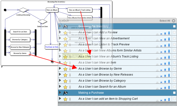
Start modeling flow for this Activity, linking Actions with other diagram elements. All Activities must have a start as well as an end point. I model my Activities so that my flow is complete. This ensures that all known paths have been captured. This step is crucial in capturing all known functionality for the high-level requirement.
Remember that this is an interactive step with the audience. The audience / customer will provide input as to the flow of the Activity from Action to Action.
Step 4: Aggregate Similar Actions to Separate Activity
If the diagram begins to flow outside of your viewable area, this is an indicator for breaking out one or more actions into a separate Activity. Several actions can be converted into one abstract action that encompasses all the functionality provided by all those actions. In the figure in step 3, the Action ‘Purchase an Item’, was created to represent another Activity diagram. The separate Activity diagram that I created was named ‘Purchasing an Item’ and contains the detailed flow for that functionality.
This step is reliant on the Tech Lead’s skill to identify similar areas of responsibility within the activity.
Step 5: Convert Activity Diagram into User Stories
After one Activity diagram is fairly complete, begin entering them into Tracker as Stories. Each Action should be converted into a user story using a consistent syntax (i.e. ‘As a <role> I can <result> so that <benefit>’).
Step 6: Repeat Steps until all Functional Requirements are Exhausted
Steps 1-5 must be repeated until all high-level functional requirements have been modeled as Activities during discussion. In the end, I will have a catalog of Activity diagrams. In the figure below, a Package Diagram displays all the Activity Diagrams that I have modeled. I like to use each of the Activities as a milestone during planning. This may or may not be ideal depending on how granular your functional requirements are.
Conclusion
There are many arguments against modeling in the agile communities, so it is important to view modeling as being supplemental to the process. In the end, our models are used to aid in the process of conveying and gathering information with the customer. Some other benefits include:
- The diagrams can serve as a documentation deliverable
- Interactive modeling along with the diagrams, which serve as a visual aid, improves customer comprehension of our software development process
- This is a great way to capture requirements when none exist
- The Activity diagram allows us to write stories in a format that follows an accompanied wireframe (if available)
- User roles can be added to Activity diagrams as swimlanes (partitions). This aids in separating functionality by use case
Rob Pak
Rob codes for a living at Carbon Five, in beautiful Santa Monica, CA.


